


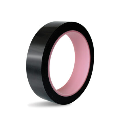








A placement machine is only as productive as its feeders. When a reel runs dry mid-shift, the options are blunt: stop the machine, pull the feeder, load a new reel, re-index and restart — or splice the new reel onto the old one while the machine keeps placing.
Splicing wins on every metric that matters. It preserves feeder calibration, avoids mechanical wear from repeated insertion, and keeps the line running at speed. Modern high-mix lines run 200 to 400 feeders per machine, and a single operator may cover several lines at once, so reel changeovers are no longer a maintenance task. They are a process discipline.
The splice tape is the weakest link in that discipline. This article covers what a splice actually has to survive, how to choose the right construction, and the standardized method that keeps splices from becoming line stops.
What a splice joint really has to survive
There is a common misconception that splice tape performance is about peel strength. Peel numbers look good on a datasheet, but peel forces during normal operation are close to negligible. The forces that actually break a splice are different:
| Force | What happens | Effect on the joint |
|---|---|---|
| Sustained shear | Feeder motor pulls continuously | Adhesive creep |
| Acceleration spikes | Rapid start-stop indexing | Load amplification |
| Dynamic tension | Reel mass changes as it unwinds | Pocket distortion, alignment drift |
| Time-dependent creep | Long dwell under load | Gradual misalignment |
A splice that holds when you tug it by hand can still fail forty minutes later under sustained shear. That is why holding power matters as much as peel adhesion, and why the joint should be pressed with uniform pressure rather than a quick thumb swipe.
Choosing the right splice tape
Selection comes down to four variables: carrier tape width, carrier tape material, ESD requirement, and whether the machine has splice sensing.
1. Match the tape to the carrier width
| Part number | Specification | For carrier tape | Packing |
|---|---|---|---|
| SMS1808C+ | 4.8 × 40 mm | 8 mm | 500 pcs/box |
| SMS1812C+ | 7 × 40 mm | 12 mm | 500 pcs/box |
| SMS1816C+ | 9.5 × 40 mm | 16 mm | 500 pcs/box |
| SMS1824C+ | 17 × 40 mm | 24 mm | 250 pcs/box |
The SMS18 series covers 8 mm through 88 mm carrier tapes. Using a tape that is too wide for the carrier means adhesive overhangs into the sprocket hole area and the pocket; too narrow and the joint has insufficient bond area.
2. Paper vs. embossed plastic carrier tape
Paper carrier tape and embossed plastic carrier tape have different surface energies and stiffness. A splice optimized for embossed plastic may not bond reliably to paper. Check with your supplier rather than assuming one construction covers both.
3. ESD requirement
If the component is ESD-sensitive, and most are, the splice should be too. Antistatic constructions are available for the standard 8 mm through 44 mm range. A non-ESD tape on an ESD carrier tape defeats the point of the carrier.
4. Machines with splice sensing
This is where most selection mistakes happen. Some placement machines detect a splice optically or mechanically, and a splice tape of the wrong thickness, color contrast or material density will trigger a sensor fault or a line stop. 18 series is rated for all SMT machines except sensitive (sensor-equipped) machines; those require a dedicated construction, typically a splice tape with holes or a metal-detectable variant. Confirm your machine model before standardizing.
SMS18 series: technical data
| Property | Typical value |
|---|---|
| Material | PET film |
| Adhesive | Acrylic |
| Peeling force (180°) | ≥ 15 N/25 mm |
| Holding power | > 100 h / 25×25 mm |
| Tensile strength at break | > 4.0 N/25 mm |
| Available widths | 8, 12, 16, 24, 32, 44, 56, 72, 88 mm |
| Colors | Yellow, black, blue, green, pink, red |
| Compliance | RoHS |
| Storage | 20–30 °C, 45–65% RH |
| Shelf life | 1 year |
Design notes. The 18 series uses a guide-and-dot alignment design: both alignment guides and dots are printed so the operator can align the joint without a jig. It is a double-sided construction, so the tape bonds both the top and bottom of the carrier tape for a joint that resists the peel mechanism from either direction. Two green tapes plus release paper, applied in one piece without a splicing tool.
Beyond the 18 series, Supplies the full splice family: single-sided splice tape, splice tape with copper buckle, sealing lead tape, sharp-corner splice tape, aluminum foil splice tape, machine splice tape and splice tape with holes, along with splicing pliers, splice cutters and splicing carts.
The six-step splice method
Most splice failures trace back to method, not material. Standardize these steps and train to them.
- Cut square, between pockets. Cut both the exhausted trailer and the new leader at exactly 90 degrees, precisely between component pockets. Cutting into a pocket leaves a partial cavity that jams the feeder indexing gear and mispresents the component to the nozzle.
- Align pockets, not edges. The objective is pocket-to-pocket spacing continuity. Aligning the cut edges but not the sprocket holes produces a one-tooth pitch error, and the machine will then present every subsequent component off-position.
- Bridge the cover tape. The carrier tape joint is only half the job. Use a cover tape splice sticker or brass shim to bridge the top cover tape. This joint has to survive the high-tension peeling mechanism without snapping, because a torn cover tape inside the feeder is a jam, and a jam is a stop.
- Apply with uniform pressure. Press the splice evenly across its full area. Finger pressure alone leaves unbonded regions that creep. A splicing tool or jig delivers repeatable pressure and prevents angular skew.
- Index slowly at first. After loading, index the feeder slowly two or three times before returning to production speed. This catches an alignment error at low energy instead of at full machine speed.
- Record it. Log the splice location in the MES and on the reel label. If a defect shows up later, “was there a splice in that section” is one of the first questions you will be asked.
Two more habits worth building: stagger splices across lanes so several feeders do not hit their splice at the same moment, and keep reels at room temperature before splicing, because cold cover tape adhesive behaves differently and is a common cause of cover tape tearing.
Failure modes and what they mean
| Symptom | Likely cause | Countermeasure |
|---|---|---|
| Joint separates in the feeder | Insufficient shear holding, or inadequate application pressure | Check holding power spec; press with a tool; verify adhesive is in date |
| Tape jams at the splice | Sprocket holes misaligned, or cut made into a pocket | Re-cut square; use a splicing jig; align holes before pressing |
| Pick error right after a splice | Pocket continuity broken, or adhesive exposed in the pocket | Align pockets not edges; use correct tape width |
| Cover tape tears during peel | Cold reel, aged adhesive, or cover tape joint too weak | Warm reels to room temperature; bridge cover tape properly |
| Sensor fault at the splice | Tape thickness or color contrast not matched to the sensor | Use a splice-with-holes or sensor-compatible construction |
| Drifting placement accuracy over time | Adhesive creep under sustained load | Check holding power; reduce dwell by splicing closer to run-out |
| Material loss at changeover | Over-stripped cover tape, or re-splicing after a bad first attempt | Standardize strip length; train to first-time-right |
The economics are not about tape price
A splice tape costs cents. A line stop costs minutes of placement time across the whole machine, plus the operator time to clear the jam, plus the risk of a mispick that becomes a defect escaping to reflow.
The useful metric is not cost per splice but splice MTBF, how many reels pass between splice-related incidents, alongside your mispick rate. Track them by feeder, by operator and by reel supplier. A pattern in that data will tell you whether your problem is material, method or hardware wear.
Two other cost levers: consolidate partial reels in the kitting area using the same tape and tools as the production floor, because kitting splices are production splices and not a lower standard; and standardize one tape and one tooling set across all shifts so results do not depend on who is working.
Color coding as a control tool
The SMS18 series is available in yellow, black, blue, green, pink and red. Beyond identification, color is a practical process control: assign a color per shift, per line or per lot so a splice can be visually traced back to when and by whom it was made. On lines running traceability requirements, this is the cheapest audit trail available.
FAQ
Can I use one splice tape for all my machines?
Not always. Standard constructions such as the SMS18 series work across all SMT machines except sensor-equipped / sensitive machines, which need a splice tape with holes or another sensor-compatible construction. Confirm your machine model before standardizing.
Is higher peel strength better?
Not by itself. Peel force matters less in operation than holding power under sustained shear and resistance to acceleration spikes. Look at both numbers.
Do I need ESD splice tape?
If the components are ESD-sensitive, yes. A non-ESD splice on an ESD carrier tape breaks the static control path at the weakest point.
Do I need a splicing tool?
It is strongly recommended. Tools control alignment and pressure, and they make results repeatable across operators and shifts. The 18 series can be applied by hand thanks to its guide-and-dot design, but a jig still reduces variation.
How should splice tape be stored?
20–30 °C at 45–65% relative humidity. Shelf life is one year. Cold or dry storage degrades adhesive performance, and an out-of-date tape will show up as creep failure rather than as a visible defect.
What carrier tape widths do you support?
8 mm through 88 mm, including 8, 12, 16, 24, 32, 44, 56, 72 and 88 mm, plus splicing tools and jigs.