







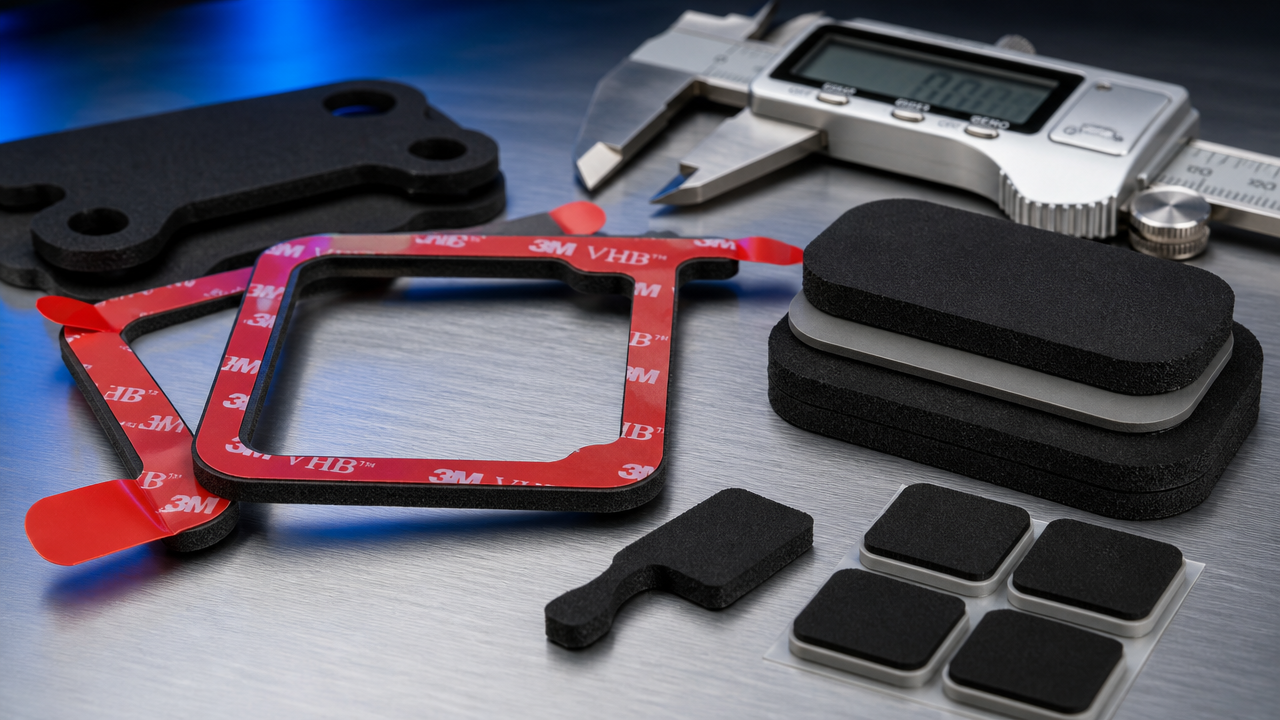
Die cutting looks like a shaping operation. In practice it is a conversion step: it turns a roll of film, foam or foil into a part that a machine or an operator can place accurately, repeatedly, and without leaving anything behind.
That framing matters because the failure modes are rarely about the outline. A gasket that is 0.15 mm out of position, a foam pad whose kerf compresses differently than its center, a shielding laminate that delaminates at the inside radius — all of these are die cutting problems, and all of them show up as assembly problems downstream.
This article covers eight industries where precision converted parts carry real functional load, the tolerances each one typically works to, and the design checks that keep a part stable from first article to the ten-thousandth piece.
Start with the cut type, not the material
Before discussing substrates, it helps to separate three decisions that get conflated:
How deep does the cut go? A kiss cut severs the adhesive and face stock but leaves the release liner intact, so the part stays on a carrier until it is dispensed. A through cut separates everything, producing loose pieces. Multi-level or “step” cutting combines both in one pass — through-cut the perimeter, kiss-cut an internal window, for example.
How is the part presented? Sheet, roll, single-up, multi-up, on a carrier with pull tabs, or on a frame for automated pick-and-place. Presentation often constrains the design more than the geometry does.
What varies across the part? If the part is a simple two-dimensional shape in one material, almost any process works. If it is a laminate of five layers with adhesive-free zones and a stepped thickness, the process choice narrows considerably.
| Process | Typical tolerance | Best for | Limit |
|---|---|---|---|
| Rotary die cutting | ±0.05 to ±0.15 mm | Thin webs, films, tapes, long runs | Tooling cost; less suited to thick stacks |
| Flatbed die cutting | ±0.10 to ±0.20 mm | Thick foams, rubber, multi-layer gaskets | Lower throughput than rotary |
| Laser / digital cutting | ±0.02 to ±0.10 mm | Prototypes, frequent design changes, fine geometry | Heat-affected edge on some polymers; slower throughput |
Typical industry tolerance bands that converters work to, drawn from publicly published equipment and market data:
| Industry | Typical parts | Working tolerance | Common process |
|---|---|---|---|
| Electronics | EMI shields, insulation films, adhesive tapes, foam gaskets | ±0.02–0.05 mm | Rotary, flatbed, laser |
| Battery & energy | Electrode insulation, separators, cell pads | ±0.02–0.05 mm | Rotary, laser |
| Medical & diagnostics | Medical tapes, dressings, diagnostic strips, wearable patches | ±0.05–0.10 mm | Rotary, digital, flatbed |
| Automotive | Gaskets, seals, NVH pads, interior trim adhesives | ±0.05–0.15 mm | Flatbed, rotary |
| Industrial sealing | Rubber, cork, PTFE, sponge gaskets | ±0.10–0.20 mm | Flatbed, rotary |
| Packaging & labels | Labels, cartons, flexible packaging | ±0.10–0.20 mm | Rotary, flatbed, digital |
| Technical textiles | Wearable components, hook-and-loop, smart fabric parts | ±0.10–0.30 mm | Digital, laser, rotary |
The tightest bands cluster exactly where you would expect: wherever a part sits against an optical surface, a sealing face, or a live electrical contact.
Case 1 — Consumer electronics: back adhesive, lens and nameplate bonding
Where: Smartphones, TWS earbuds, wearables, smart home devices. Supplies die-cut back adhesive for fixing windows and lenses, mobile phone nameplates, earphone and microphone accessories, LCD frames and battery plate buffering pads.
The constraint: These parts bond dissimilar surfaces — glass to polycarbonate, anodized aluminium to PET, coated lens to housing — and the bond line is usually under 0.2 mm. Adhesive squeeze-out at the edge is visible on a transparent window, and a pad that is 0.1 mm too thick changes the stack height enough to lift a cover or preload a button.
What works: A die-cut part with a controlled adhesive coat weight, a carrier that supports hand or machine placement, and pull tabs positioned so the operator never touches the bond surface. Where the part sits behind a display or camera window, the die cut also has to be optically clean — no fiber debris, no adhesive stringing at the corners.
How to verify: Measure stack height across a full assembly build, not on a single prototype. Check for edge ooze after 72 hours at elevated temperature rather than immediately after assembly; acrylic adhesives continue to wet out, and a part that looked clean at t = 0 can creep into view later.
Case 2 — Display and backlight modules: light control is a mechanical problem
Where: LCD reflective films, diffuser stacks, light guide frames, bezel light-blocking and black-black shading tape in phones, tablets, automotive clusters and industrial HMIs.
The constraint: Optical films are cut to tighter tolerances than most structural parts because the edges define the active area. A shading frame that is 0.1 mm too narrow lets light leak at the bezel; one that is 0.1 mm too wide covers pixels. The other issue is compression: foams used in display gaskets recover slowly, so a stack assembled under pressure behaves differently after a day of relaxation.
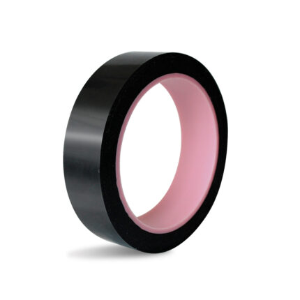
What works: Kiss-cut frames on a stable liner, cut with a die that leaves a clean vertical edge rather than a tapered one. Black-black shading tape — black adhesive on black film — is die cut to narrow widths and needs a liner that releases without lifting the adhesive. Where the module later goes through a bonding or coating step, the film must be silicone-free; this is the same contamination mechanism described in our article on silicone-free high-temperature tape for optical modules.
How to verify: Backlight leak test on a dark pattern at the first article stage, plus a dimensional check after 24-hour relaxation at room temperature. Measure after relaxation, not off the press.
Case 3 — EMI shielding and grounding gaskets
Where: Shielding cans, connector housings, laptop and tablet chassis, 5G modules, automotive radar housings.
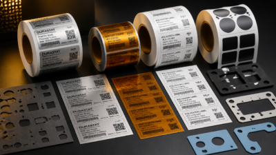 The constraint: A shielding gasket has to satisfy two requirements at once: it must compress to a target deflection under a known closure force, and it must provide a continuous conductive path. Both are destroyed by poor converting. A conductive fabric wrapped over a foam core needs the fabric to meet at the seam without a gap; a cut edge that frays creates intermittent contact; an inside radius that is too tight cracks the metallized layer.
What works: Multi-layer laminating before cutting, so foil, fabric and foam are bonded into one web before the die touches it. Cutting is then a single operation on a composite rather than an assembly of separate die-cut layers — registration between layers stops being a variable. Runs precision multi-layer laminating and die cutting in the same workflow for exactly this reason.
How to verify: Compression-deflection curve on the finished part (not just the raw foam), plus a shielding effectiveness check on the assembled housing. A gasket that compresses correctly but has a cracked metallized layer will pass the mechanical test and fail the RF test.
Case 4 — Battery and energy storage: where a burr is a safety issue
Where: Cell insulation sheets, tab insulation, module and pack pads, busbar covers, separator and termination tape in lithium cells and ESS packs.
The constraint: Tolerance here is not cosmetic. An insulation sheet that is short by 0.2 mm can expose a live edge; a metallic burr from a foil laminate cut is a potential internal short circuit. Battery insulation parts are routinely specified to ±0.02–0.05 mm, the same band as electronics, and the cut edge must be free of conductive debris.
What works: Laser or precision rotary cutting for foil-containing laminates, with a defined deburring and cleaning step. Cell pads use closed-cell foam or silicone-free elastomer with a verified compression set, because the pad maintains preload through thousands of charge cycles — a pad that takes a permanent set stops holding the cell, and the module loosens.
How to verify: Optical inspection of every edge on foil laminates during pilot, hipot testing on the assembled module, and compression set data at the actual operating temperature rather than at 23 °C.
Case 5 — Automotive: NVH pads, seals and harness fixing
Where: Interior trim anti-rattle pads, door and lamp seals, HVAC gaskets, harness tapes and clips, battery pack thermal interface and insulation parts.
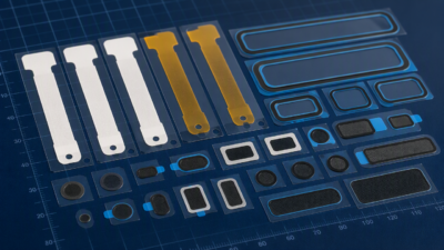 The constraint: Automotive parts live in the widest environment of any category here — roughly −40 °C to +85 °C in the cabin, higher under-hood, plus humidity, salt spray and UV. The die cut has to hold its shape through thermal cycling, and the adhesive has to survive it without oozing or drying out. Working tolerances are looser than electronics, typically ±0.05–0.15 mm, but the material qualification burden is heavier.
What works: Closed-cell foams and EPDM-based seals cut on flatbed for thicker sections, rotary for thin webs. For interior parts, low-VOC and fogging requirements drive material selection as much as adhesion does. Where a part is applied by robot, the liner release force window matters more than the die tolerance — a liner that releases inconsistently will stall an automated cell faster than a 0.1 mm dimensional error ever will.
How to verify: Thermal cycling with the part in the assembled state, plus peel and shear testing after conditioning. Test after aging, not on fresh samples.
Case 6 — Medical and diagnostics: the paperwork is part of the part
Where: Wound dressings, transdermal patch liners, diagnostic test strip substrates, ECG electrode pads, wearable biosensor patches, surgical drape fenestrations.
The constraint: Published market data puts medical precision die cutting at roughly 15.7% of the global precision die cutting market, valued around USD 1.32 billion in 2025 and growing at about 6.5% CAGR. The number matters less than the reason: medical converting requires ISO 13485 quality systems, validated cleanroom environments, and lot-level material traceability to satisfy FDA 21 CFR Part 820. That is a qualification barrier, and it is why this segment favors established converters over low-cost shops.
What works: Tolerances of ±0.05–0.10 mm are typical, with biocompatibility documentation for anything contacting skin or fluids. Wearable patches are the demanding subset — they combine a skin-contact adhesive, a flexible substrate, often a conductive element, and a liner that must release cleanly while the patient is wearing the device.
How to verify: Full material certification and lot traceability from the converter, plus validation of the release liner under the intended application method. A patch that releases too hard gets distorted during application, which changes the adhesive contact area and therefore the wear time.
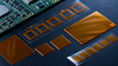 Case 7 — PCB and SMT process parts: high-temperature die-cut masking
Where: Gold finger protection, wave solder masking, selective soldering shields, PCB back adhesive, and pre-cut masking dots for connector and contact protection.
The constraint: This is the case where a die-cut part replaces hand-applied tape, and the win is consistency. Supplies pre-cut polyimide masking dots and green polyester masking dots for exactly this: a dot placed by hand from a roll is rarely in the same place twice, while a die-cut dot is repeatable, which is what automated placement needs.
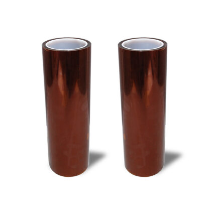
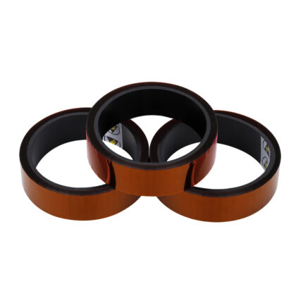
What works: Polyimide for anything above roughly 200 °C, polyester for lower-temperature and cost-sensitive applications. The die cut must sit on the solder mask rather than on the gold surface where the process allows, because adhesion to solder resist is more predictable than adhesion to a polished contact. For the specific requirements of protecting edge contacts, see gold finger masking tape: six application cases.
How to verify: Run the actual reflow or wave profile with a thermocouple, then inspect the protected surface under magnification after removal. Most “residue” complaints in this category trace back to a peak temperature above the tape rating rather than to the tape itself.
Case 8 — Semiconductor and optical module converting
Where: Polyimide dams for encapsulation, wafer dicing and back grinding tape converted to frame format, temporary fixing films, thermally conductive pads.
The constraint: Two things dominate. First, cleanliness — silicone contamination from a release liner or an adhesive will cause bonding failure and wire bond NSOP problems downstream, which is why semiconductor converting is a controlled-environment operation. Converts and slits UV dicing tape and wafer back grinding tape, and operates a class 10K cleanroom for these products.
Second, dimensional stability at very small feature sizes. A PI dam for resin bleed control has a defined height and width; if the die cut tapers, the dam height varies and the resin finds the low spot.
How to verify: Measure the cut cross-section, not just the top surface, and confirm the part survives the encapsulation temperature without lifting. For the tape selection logic behind dicing and grinding, see adhesive tape in semiconductor packaging: 7 application cases.
DFM checks before you send a drawing
Most converting problems are fixed at the drawing stage for the cost of an email. Ten checks that catch the majority:
- Identify the functional edge. Not every dimension needs a tight tolerance. Mark the edges that matter; let the rest run at ±0.2 mm. Tolerancing everything tightly raises cost without improving function.
- Radius every corner. An inside radius below roughly 0.3 mm concentrates stress and starts a tear during dispensing or thermal cycling.
- Keep bridges and narrow webs above 0.5 mm. Narrow features twist, stretch and break during matrix stripping. If the design needs something narrower, change the presentation rather than the die.
- Holes should be at least 1.5× the material thickness in diameter, with adequate spacing between them.
- Specify kiss-cut depth with a tolerance, and state which layer must remain intact. “Cut through the adhesive, leave the liner” is not a specification on its own.
- Define presentation explicitly: roll or sheet, single-up or multi-up, pull tabs, waste matrix removal method, and whether the part is picked by hand, by dispenser or by a placement head.
- Call out material direction (MD/TD) for films. Polyimide and PET are not dimensionally isotropic; a part that shrinks differently in one axis will drift across a long run.
- State the environment. Cleanroom class, ESD requirement, silicone-free requirement, and packaging. A part that is correct but arrives in the wrong packaging fails incoming inspection.
- Name the mating surface. Adhesion to a textured powder coat and to polished glass are different problems. The converter can only select an adhesive if they know what it is bonding to.
- Plan a three-stage qualification: first article for fit, small batch for process stability, then production with defined inspection frequency.
Common converting defects and where they come from
| Defect | Usual cause | Countermeasure |
|---|---|---|
| Edge burr or stringing | Dull die, wrong clearance, adhesive too soft for the cut | Sharpen or change tooling; adjust cut temperature; consider laser for fine features |
| Adhesive residue on liner | Kiss-cut depth too deep, adhesive cold-flowing | Reduce depth; specify a stable-coat adhesive; shorten storage before use |
| Parts fall out during matrix stripping | Bridge too narrow, tack too low, strip angle wrong | Widen bridges; adjust release liner; change strip geometry |
| Dimensional drift across a run | Web tension change, material relaxation, die wear | Tension control, in-process measurement, defined die life |
| Delamination of a laminate part | Insufficient laminating pressure or incompatible adhesive between layers | Laminate before cutting; verify layer-to-layer peel |
| Curl or lift after application | MD/TD mismatch, insufficient adhesive wet-out, substrate surface energy too low | Set material direction; check surface energy; verify with a dyne test |
| Registration error between layers | Stacking separate die-cut layers instead of laminating first | Multi-layer laminating before die cutting |
| Contamination (fiber, particle, silicone) | Wrong cleanroom class, wrong glove or liner | Class 10K or better converting; silicone-free liners; ESD packaging |
Frequently asked questions
Kiss cut or through cut?
Kiss cut when the part is dispensed from a liner by hand or machine. Through cut when parts are stacked, counted or fed loose. If a design needs both — a through-cut outline with an internal window — it is a step-cut operation and should be specified as such.
How small can a feature be?
Practical limits depend more on the material than on the machine. Narrow bridges under 0.5 mm and holes under roughly 1.5× material thickness are where yields start to drop regardless of process. Laser extends the limit for fine geometry but introduces a heat-affected edge that some adhesives do not tolerate.
Roll or sheet?
Roll for automated dispensing and high volume. Sheet for thick materials, large parts, and low volume where tooling cost dominates. Automated placement almost always wants roll.
Why did the first article fit but production drift?
Usually one of four: material relaxation after converting, web tension differences between the sample run and production, die wear over a long run, or temperature and humidity differences between the converter and the assembly floor. Measure parts after 24-hour relaxation, and ask for the production tension settings.
What cleanroom class do I need?
Class 10K is a common baseline for electronics converting; display optical films and medical parts often require tighter. The requirement should be driven by what the part touches — a gasket inside a sealed housing needs less than a film on an optical surface.
When is silicone-free mandatory?
Whenever the part precedes a bonding, coating, painting or plating step, or sits near an optical surface. Silicone contamination is invisible, survives the process, and shows up as delamination or coating defects that appear unrelated to the tape.